
Welcome to our forum. A Message To Our New and Prospective Members . Check out our Forum Rules. Lets keep this forum an enjoyable place to visit.
Currently working on errors from the latest (SimplePress) forum update. Many issues have been resoled and others are being worked on. Thank you for your patience.

 Log In
 Register


 Topic RSS
 (2 votes)
Regulars
 Offline


Members
Offline


Yeah, you'd have a point here. LOL
Besides, one could get a close enough visual effect with an LED under a tube like some of the "tube preamps" out on the market for guitar these days.
"This young wine may have a lot of tannins now, but in 5 or 10 years it is going to be spectacular, despite the fact that right now it tastes like crude oil. You know this is how it is supposed to taste at this stage of development." ~ Itzhak Perlman
Regulars
Offline
There's a pawn shop about 2 miles away that has a Khor hc602 violin for sale. It was in a flood and is in bad shape. the Varnish is horrible and the peg box is warped. It was probably submerged. The ebony finger board is discolored and its missing the A string. But other then that...... HA!!
I should see if they'll sell it real cheap for a bit of steampunkery. I did attempt to play it and it sounds kind of dull and lifeless. But in a steampunk arena, its not how it sounds, it how it looks.... maybe we can start a new topic on SteamPunk instead of filling these topics with our own agenda to take over the music world. ![]()
"I find your lack of Fiddle, disturbing" - Darth Vader
New member
Offline
Okay, so I have decided to try my hands on an FET preamp. I've looked at the schematics and I don't know how to wire a pots for volume and tone control, any ideas? Also, for the output, would it make sense to solder a double end output for a headphone jack and a speaker/amp jack?
Regulars
Offline
The field effect transistor is not so simple a device if you do not have some electronics background. To use them in a preamp, such as darlington pairs or as a gain type circuit has limitations and considerations for feedback to keep the gate current within required operating limits. You also need to have another active filter to remove noise as Db signal loss or a signal to noise ratio drop.
A potentiometer is used as an attenuator in these circuits. There are 3 terminals on most "standard" types. The 2 ends will give you the maximum resistance at what its watt rating is. The center post is the adjustable one. They are typically a carbon slide wiper on the inside or a mechanical connection to internal carbon (or sand) resistors. It can be used from either side and adjusted accordingly.
You can connect the staged amp to both ends of a stereo jack, but you will get mono out (and probably impedance loss). You need to have 2 circuits delivering a different audio channel or a combiner circuit to join all channels to a single output source. Your speakers or headphones will be rated at an Ohm of probably 4 or 8 for low end speakers. you need to take this into consideration for your output impedance to deliver as much signal to your speakers without impedance mismatch or again, you will get a degridated or distorted signal out - or possibly blow your amp or the speakers themself by over driving them.
Again, I would direct you towards Fiddlerman's original thoughts and purchase one. There are problems that can arise and safety issues if you are not familiar with electronics especially AC power sources, power supplies, capacitors and rectifiers.
"I find your lack of Fiddle, disturbing" - Darth Vader
Members
Offline

Circuit design is kind of heading outside the scope of this forum, and even this section, but I'll try to give you an idea of how you might start, silver.
Bear in mind, I haven't made a preamp for the exact sort of piezo pickup mentioned in this thread. But I did end up making an FET preamp from scratch for my electric violin. Piezo elements may not be identical, but it should work well enough to give you a starting point for tinkering, if you are the tinker sort.
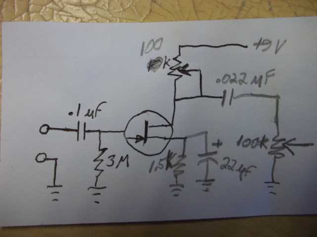
The FET I used was an MPF102. Fairly common type, I got it at Radio Shack. Now to get this to work as good as possible with whatever piezo element you use and whatever sort of amp you are running it into will likely take some tinkering with some of the components. The .022 uF cap is the one that will have the most effect on tone. I think I ended up changing it to a .047uF. The 100k potentiometer at the top is one you don't change after you find the best setting for it. It is like the bias adjustment on old tube amps. You need to measure the voltage between the junction where that goes into the transistor and the ground and adjust it. Somewhere between 4.5 and 6 volts you'll get the best sound. It can vary, depending on what kind of amplifier you end up sending the output to and what other changes you make to get the tone you like.
With my electric, I think I also ended up adding a 10K resistor at the input end because the piezo element was driving this little circuit harder than I wanted. I wanted it to only start to edge into distortion when I play hard.
Unless you really like tinkering, though, they have quite a few choices of ready built preamps on places like Ebay for piezo pickups that have eq, and etc built in. That would probably be a lot easier. If you do a search there, you'll find a few hundred options, try searching with: piezo guitar preamp
I built mine from scratch for my electric because I like doing things like that, and I didn't like how the piezo element was overdriving the poor little op-amp circuit the manufacturer put in it. It sounded too "hot" to me, probably it was a reaction to assorted complaints people apparently had of some other electrics not being "powerful" enough.
But if you are keen on building your own preamp from scratch, that schem is about what I started with. Your mileage may vary. LOL
"This young wine may have a lot of tannins now, but in 5 or 10 years it is going to be spectacular, despite the fact that right now it tastes like crude oil. You know this is how it is supposed to taste at this stage of development." ~ Itzhak Perlman